The power cycle converts thermal energy to electric energy. There are two options for modeling the power cycle:
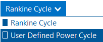
•The Rankine-cycle model is for Rankine-cycle steam engines with two open feed-water heaters, and a pre-heater, boiler and super-heater. This regression model was developed from a detailed first-principles basis Rankine cycle model and calculates cycle performance over the expected operating range by modeling each cycle component at off-design conditions. The model assumes that deviation in cycle performance at off-design conditions is independent of cycle design and only a function of deviation from the user-specified design point. This model is fast, flexible, and accurate, and suitable for modeling most conventional CSP power cycles.
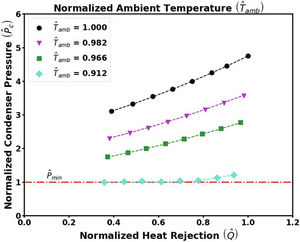
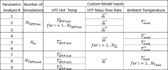
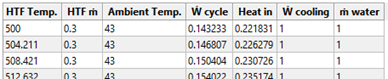
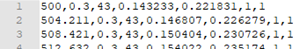
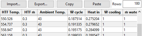
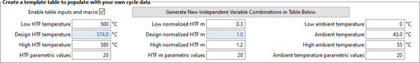
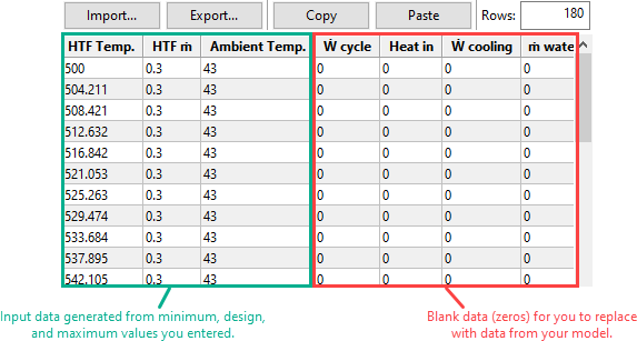
•The user-defined power cycle model allows you to use data from your own power cycle model in SAM, and can be used to model Rankine or other types of power cycles. It requires that you provide values for general power cycle parameters along with a tables of data showing the electrical power generated over a range of HTF mass flow rates, ambient temperatures, and ambient temperatures. SAM uses this data to build a power cycle regression model that considers single variable effects and two variable interactions.
Note. If you are modeling a supercritical Carbon dioxide (sCO2) cycle, you can use the sCO2 Cycle Integration macro with the NREL Supercritical Carbon Dioxide (sCO2) Python model. SAM 2020.2.29 is the most recent version to include an sCO2 option on the Power Cycle page.
The power cycle model is described in the following publications listed on the SAM website at https://sam.nrel.gov/concentrating-solar-power/csp-publications.html:
•Chapter 4 of Wagner M, 2008. Simulation and Predictive Performance Modeling of Utility-Scale Central Receiver System Power Plants. Master of Science Thesis. University of Wisconsin-Madison
•Chapter 3 of Wagner, M. J.; Gilman, P. (2011). Technical Manual for the SAM Physical Trough Model. 124 pp.; NREL Report No. TP-5500-51825.
•Hamilton T.; Newman, A.; Wagner. M.; Braun, R. (2020). Off-design Performance of Molten Salt-driven Rankine Cycles and its Impact on the Optimal Dispatch of Concentrating Solar Power Systems. Energy Conversion and Management Vol 20 113025.
System Design Parameters
The system design parameters are from the System Design page, where you can define the design-point parameters of the entire power tower system.
Power cycle gross output, MWe
The power cycle electrical output at the design point, not accounting for parasitic losses.
Estimated gross to net conversion factor
An estimate of the ratio of the electric energy delivered to the grid to the power cycle's gross output to account for parasitic losses.
Estimated net output (nameplate), MWe
The power cycle nominal capacity, calculated as the product of the gross output and gross-to-net conversion factor.
Estimated Net Output at Design (MWe) = Design Gross Output (MWe) × Estimated Gross to Net Conversion Factor
Cycle thermal efficiency
The thermal to electric conversion efficiency of the power cycle at the design point.
Cycle thermal power, MWt
The turbine thermal input at the power cycle inlet to operate at the design point.
HTF hot temperature, °C
The design temperature of the hot heat transfer fluid at the power cycle block inlet.
HTF cold temperature, °C
The design temperature the cold heat transfer fluid at the power cycle outlet.
General Design Parameters
Pumping power for HTF through power block, kW/kg/s
A coefficient used to calculate the electric power consumed by pumps to move heat transfer fluid through the power cycle.
Fraction of thermal power needed for standby
The fraction of the turbine's design thermal input required from storage to keep the power cycle in standby mode. This thermal energy is not converted into electric power. Default is 0.2.
Power block startup time, hours
The time in hours that the system consumes energy at the startup fraction before it begins producing electricity. If the startup fraction is zero, the system will operate at the design capacity over the startup time. Default is 0.5 hours.
Fraction of thermal power needed for startup
The fraction of the turbine's design thermal input required by the system during startup. This thermal energy is not converted to electric power. Default is 0.75.
Minimum turbine operation
The fraction of the nameplate electric capacity below which the power block does not generate electricity. Whenever the power block output is below the minimum load and thermal energy is available from the solar field, the field is defocused. For systems with storage, solar field energy is delivered to storage until storage is full. Default is 0.25.
Maximum turbine over design operation
The maximum allowable power block output as a fraction of the electric nameplate capacity. Whenever storage is not available and the solar resource exceeds the design value of 950 W/m2, some heliostats in the solar field are defocused to limit the power block output to the maximum load. Default is 1.05.
Cycle design HTF mass flow rate, kg/s
The hot heat transfer fluid (HTF) mass flow rate at the design point.
HTF Mass Flow Rate (kg/s) = Cycle Thermal Power (MWt) × 1000 (kW/MW) ÷ Average HTF Cp (KJ/kg·K) ×
( HTF Hot Temperature (°C) - HTF Cold Temperature (°C) )