The power cycle converts thermal energy to electric energy. The power cycle is assumed to consist of a superheated two-stage turbine with multiple extractions for feedwater heating and a reheat extraction between the high and low pressure turbine stages. You specify the design-point efficiency of this cycle on the Power Cycle page, and SAM models the part-load behavior with normalized performance curves as a function of steam inlet temperature, mass flow rate, and ambient temperature. The ambient temperature correction uses the wet-bulb temperature for wet-cooled systems and hybrid systems and the dry-bulb temperature for dry cooled and hybrid cooled systems.
The power cycle page displays variables that specify the design operating conditions for the steam Rankine cycle used to convert thermal energy to electricity.
Plant Design
Design turbine gross output, MWe
The power cycle's design output, not accounting for parasitic losses.
Estimated gross to net conversion factor
An estimate of the ratio of the electric energy delivered to the grid to the power cycle's gross output. SAM uses the factor to calculate the power cycle's nameplate capacity for capacity-related calculations, including the estimated total cost per net capacity value on the Installation Costs page, and the capacity factor reported in the results.
Net nameplate capacity, MWe
The power cycle's nameplate capacity, calculated as the product of the design gross output and estimated gross to net conversion factor.
Net Nameplate Capacity (MWe) = Design Gross Output (MWe) × Estimated Gross to Net Conversion Factor
Rated cycle efficiency
The thermal to electric conversion efficiency of the power cycle under design conditions.
Design thermal input power, MWt
The turbine's design thermal input. It is the thermal energy required at the power block inlet for it to operate at its design point, as defined by the value of the nameplate electric capacity and an estimate of the parasitic losses: Design thermal power = nameplate electric capacity + total parasitic loss estimate. (See the Parasitics page for a description of the total parasitic loss estimate.)
High pressure turbine inlet pressure, bar
The inlet pressure of the high pressure turbine at design. This is one of the values necessary to define the cycle at design. Current steam properties are limited to 190 bar, so this pressure should be set lower than 190 bar so that the property calculations do not fail at higher pressures calculated upstream of the turbine. The simulation may stop or produce warnings if the property routing encounters pressures greater than 190 bar.
High pressure turbine outlet pressure, bar
The outlet pressure of the high pressure turbine at design. This is another value necessary to define the cycle at design.
Design reheat mass flow rate fraction
The fraction of steam mass flow rate that exits the high pressure turbine and enters the reheater. The remaining flow is transferred to the feedwater heaters for use in preheating.
Fossil backup boiler LHV efficiency
The auxiliary fossil backup boiler's lower heating value efficiency, used to calculate the quantity of natural gas required by the boiler.
If your system includes an auxiliary boiler, choose a fossil dispatch mode and define the fossil fill fractions as described below.
Steam cycle blowdown fraction
The fraction of the steam mass flow rate in the power cycle that is extracted and replaced by fresh water. This fraction is multiplied by the steam mass flow rate in the power cycle for each hour of plant operation to determine the total required quantity of power cycle makeup water. The blowdown fraction accounts for water use related directly to replacement of the steam working fluid. The default value of 0.013 for the wet-cooled case represents makeup due to blowdown quench and steam cycle makeup during operation and startup. A value of 0.016 is appropriate for dry-cooled systems to account for additional wet-surface air cooling for critical Rankine cycle components.
Plant Cooling Mode
Condenser type
Choose either an air-cooled condenser (dry cooling), evaporative cooling (wet cooling), or hybrid cooling system.
In hybrid cooling a wet-cooling system and dry-cooling share the heat rejection load. Although there are many possible theoretical configurations of hybrid cooling systems, SAM only allows a parallel cooling option.
Ambient temp at design, ºC
The ambient temperature at which the power cycle operates at its design-point-rated cycle conversion efficiency. For the air-cooled condenser option, use a dry bulb ambient temperature value. For the evaporative condenser, use the wet bulb temperature.
Reference Condenser Water dT, ºC
For the evaporative type only. The temperature rise of the cooling water across the condenser under design conditions, used to calculate the cooling water mass flow rate at design, and the steam condensing temperature.
Approach temperature, ºC
For the evaporative type only. The temperature difference between the circulating water at the condenser inlet and the wet bulb ambient temperature, used with the ref. condenser water dT value to determine the condenser saturation temperature and thus the turbine back pressure.
ITD at design point, ºC
For the air-cooled type only. Initial temperature difference (ITD), difference between the temperature of steam at the turbine outlet (condenser inlet) and the ambient dry-bulb temperature.
Note. When you adjust the ITD, you are telling the model the conditions under which the system will achieve the thermal efficiency that you've specified. If you increase the ITD, you should also modify the thermal efficiency (and/or the design ambient temperature) to accurately describe the design-point behavior of the system. The off-design penalty in the modified system will follow once the parameters are corrected.
Condenser pressure ratio
For the air-cooled type only. The pressure-drop ratio across the air-cooled condenser heat exchanger, used to calculate the pressure drop across the condenser and the corresponding parasitic power required to maintain the air flow rate.
Minimum condenser pressure, inHg
The minimum condenser pressure in inches if mercury prevents the condenser pressure from dropping below the level you specify. In a physical system, allowing the pressure to drop below a certain point can result in physical damage to the system. For evaporative (wet cooling), the default value is 1.25 inches of mercury. For air-cooled (dry cooling), the default is 2 inches of mercury. For hybrid systems, you can use the dry-cooling value of 2 inches of mercury.
Cooling system part load levels
The cooling system part load levels tells the heat rejection system model how many discrete operating points there are. A value of 2 means that the system can run at either 100% or 50% rejection. A value of three means rejection operating points of 100% 66% 33%. The part load levels determine how the heat rejection operates under part load conditions when the heat load is less than full load. The default value is 2, and recommended range is between 2 and 10. The value must be an integer.
Operation
Low resource standby period, hr
During periods of insufficient flow from the heat source due to low thermal resource, the power block may enter standby mode. In standby mode, the cycle can restart quickly without the startup period required by a cold start. The standby period is the maximum number of hours allowed for standby mode. This option is only available for systems with thermal storage. Default is 2 hours.
Fraction of thermal power needed for standby
The fraction of the turbine's design thermal input required from storage to keep the power cycle in standby mode. This thermal energy is not converted into electric power. Default is 0.2.
Startup time, hr
The time in hours that the system consumes energy at the startup fraction before it begins producing electricity. If the startup fraction is zero, the system will operate at the design capacity over the startup time. Default is 0.5 hours.
Fraction of thermal power needed for startup
The fraction of the turbine's design thermal input required by the system during startup. This thermal energy is not converted to electric power. Default is 0.75.
Minimum operation fraction
The fraction of the nameplate electric capacity below which the power block does not generate electricity. Whenever the power block output is below the minimum load and thermal energy is available from the solar field, the field is defocused. For systems with storage, solar field energy is delivered to storage until storage is full. Default is 0.25.
Max over design operation fraction
The maximum allowable power block output as a fraction of the electric nameplate capacity. Whenever storage is not available and the solar resource exceeds the design value of 950 W/m2, some heliostats in the solar field are defocused to limit the power block output to the maximum load. Default is 1.05.
Fossil dispatch mode
The fossil dispatch mode determines how the optional auxiliary fossil (natural gas) backup boiler is configured and how it operates. Use the fossil fill fraction input under Dispatch Control to determine when the auxiliary boiler operates. Use the fossil backup boiler LHV efficiency value under Plant Design to define the boiler's lower heating value efficiency.
If your system has an auxiliary fossil backup boiler, and you want to account for fuel costs in the financial model, you should assign a fossil fuel cost on the Operating Costs page.
Note. If the Fossil fill fraction under Dispatch Control is zero for all periods, the system does not include an auxiliary fossil backup boiler, and you can ignore the fossil dispatch mode input.
Minimum backup level
In the Minimum Backup Level mode, the auxiliary boiler is in parallel with the power cycle and supplies heat to steam at the power cycle inlet when the solar field thermal output falls below the level defined by the fossil fill fractions and weekday/weekend schedules.
For example, for an hour with a fossil fill fraction of 1.0 when solar energy delivered to the power cycle is less than that the design thermal input power, the auxiliary boiler would supply enough energy to "fill" the missing heat so that the thermal power at the power cycle inlet is at the design point. If, in that scenario, solar energy from the field is driving the power cycle at full load, the auxiliary boiler would not operate. For a fossil fill fraction of 0.75, the auxiliary boiler would only be fired when solar output drops below 75% of the power cycle's design thermal input power.
Supplemental operation
In the Supplemental Operation mode, the auxiliary boiler is in parallel with the power cycle and supplies sufficient heat to the steam at the power cycle inlet for the power cycle to operate at its design point, where the design point is determined by the fossil fill fractions and weekday/weekend schedules.
Operation of the power cycle in a given hour is constrained by the Max turbine over design operation fraction and Minimum operation fraction. For hours that the energy added by the auxiliary backup boiler is insufficient to meet the minimum requirement, the backup boiler is not dispatched.
Topping mode
In the Topping mode, the auxiliary boiler is in series with the power cycle, and supplies heat to the steam as it enters the power cycle whenever the steam temperature at the solar field outlet is less than the design field outlet temperature defined on the Solar Field page. In topping mode, the auxiliary backup boiler does not operate at night.
For the topping mode option, ignore the fossil fill fraction inputs. The auxiliary boiler will operate based on the field outlet steam temperature rather than based on the fossil fill fractions.
Hybrid Cooling Dispatch
When you choose Hybrid as the condenser type, the hybrid dispatch table specifies how much of the cooling load should be handled by the wet-cooling system for each of 6 periods in the year. The periods are specified in the matrices at the bottom of the Thermal Storage page. Each value in the table is a fraction of the design cooling load. For example, if you want 60% of heat rejection load to go to wet cooling in Period 1, type 0.6 for Period 1. Directing part of the heat rejection load to the wet cooling system reduces the total condenser temperature and improves performance, but increases the water requirement. SAM sizes the wet-cooling system to match the maximum fraction that you specify in the hybrid dispatch table, and sizes the air-cooling system to meet the full cooling load.
System Availability
System availability losses are reductions in the system's output due to operational requirements such as maintenance down time or other situations that prevent the system from operating as designed.
Notes.
To model curtailment, or forced outages or reduction in power output required by the grid operator, use the inputs on the Grid Limits page. The Grid Limits page is not available for all performance models.
For the PV Battery model, battery dispatch is affected by the system availability losses. For the PVWatts Battery, Custom Generation Profile - Battery, and Standalone Battery battery dispatch ignores the system availability losses.
To edit the system availability losses, click Edit losses.
The Edit Losses window allows you to define loss factors as follows:
•Constant loss is a single loss factor that applies to the system's entire output. You can use this to model an availability factor.
•Time series losses apply to specific time steps.
SAM reduces the system's output in each time step by the loss percentage that you specify for that time step. For a given time step, a loss of zero would result in no adjustment. A loss of 5% would reduce the output by 5%, and a loss of -5% would increase the output value by 5%.
Dispatch Control
The dispatch control periods determine the following:
•For a plant with hybrid cooling, the timing of wet-cooling fractions when the plant cooling mode Condenser type is Hybrid.
•For a plant with an auxiliary fossil backup boiler, the timing and level of the backup boiler.
Notes. If your analysis involves PPA price multipliers defined on the Revenue page, you should verify that the dispatch control schedules are consistent with the TOD factor schedules.
Hybrid cooling fraction
For each period defined in the weekday and weekend schedules, specify how much of the cooling load should be handled by the wet-cooling system.
Each value in the table is a fraction of the design cooling load. For example, if you want 60% of heat rejection load to go to wet cooling in Period 1, type 0.6 for Period 1. Directing part of the heat rejection load to the wet cooling system reduces the total condenser temperature and improves performance, but increases the water requirement. SAM sizes the wet-cooling system to match the maximum fraction that you specify in the hybrid dispatch table, and sizes the air-cooling system to meet the full cooling load.
Fossil fill fraction
The fossil fill fraction and weekday/weekend schedules determine when and at what power level the auxiliary fossil backup boiler operates.
Note. If you choose the topping mode option for the fossil dispatch mode, the fossil fill fraction does not affect the operation of the auxiliary backup boiler, so you can ignore these inputs.
To model a system with no backup boiler, set the fossil fill fraction for all periods to zero.
To model a system with an auxiliary fossil backup boiler, first choose a fossil dispatch mode input under Operation to define the boiler's configuration. Then, define the dispatch schedules as described below, and set the fossil fill fraction for each period that you want the backup boiler to operate. A fossil fill fraction of 1 is equivalent to 100% of the design thermal input power. A fossil fill fraction of zero is equivalent to no fossil backup. For example, if you specify a fossil fill fraction of 0.3 for Period 1, the auxiliary boiler will supply heat to the steam at the power cycle inlet to up to 30% of the power cycle design thermal input power during Period 1.
If your system has an auxiliary fossil backup boiler, and you want to account for fuel costs in the financial model, you should assign a fossil fuel cost on the Operating Costs page.
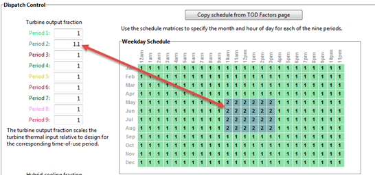
Defining Dispatch Schedules
The storage dispatch schedules determine when each of the nine periods apply during weekdays and weekends throughout the year.
If your analysis includes PPA price multipliers and you want to use the same schedule for the multipliers and for the power cycle dispatch control, click Copy schedule from TOD Factors page to apply the TOD Factors schedule matrices to the dispatch schedule matrices.
To specify a weekday or weekend schedule:
1.Assign values as appropriate to the Hybrid Cooling and Fossil Fill fractions for each of the up to nine periods.
2.Use your mouse to draw a rectangle in the matrix for the first block of time that applies to period 2.
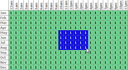
3.Type the number 2.

4.SAM shades displays the period number in the squares that make up the rectangle, and shades the rectangle to match the color of the period.
5.Repeat Steps 2-4 for each of the remaining periods that apply to the schedule.