System Design Point Parameters
These values are from the System Design page are for reference.
Storage System
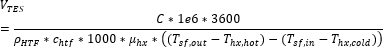
TES thermal capacity, MWht
The equivalent thermal capacity of the storage tanks, assuming the thermal storage system is fully charged. This value does not account for losses incurred through the heat exchanger for indirect storage systems. See Equations for Calculated Values.
Height of HTF when tank is full, m
The height of the cylindrical volume of heat transfer fluid in each tank.
Minimum tank fluid height, m
The minimum allowable height of fluid in the storage tank(s). The mechanical limits of the tank determine this value.
Total tank volume, m3
SAM calculates the total heat transfer fluid volume in storage based on the storage hours at full load and the power block design turbine thermal input capacity. The total heat transfer fluid volume is divided among the total number of tanks so that all hot tanks contain the same volume of fluid, and all cold tanks contain the same volume of fluid. See Equations for Calculated Values.
Number of equivalent tank pairs
The number of parallel hot-cold storage tank pairs. Increasing the number of tank-pairs also increases the volume of the heat transfer fluid exposed to the tank surface, which increases the total tank thermal losses. SAM divides the total heat transfer fluid volume among all of the tanks, and assumes that each hot tank contains an equal volume of fluid, and each cold tank contains and equal volume.
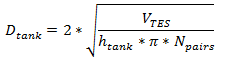
Tank diameter, m
The diameter of a storage tank, assuming that all tanks have the same dimensions. SAM calculates this value based on the specified height and storage volume of a single tank, assuming that all tanks have the same dimensions. See Equations for Calculated Values.
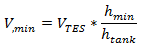
Min fluid volume, m3
The volume of fluid in a tank that corresponds to the tank's minimum fluid height specified above. See Equations for Calculated Values.
Loss coefficient from the tank, W/m2-K
The thermal loss coefficient for the storage tanks. This value specifies the number of thermal watts lost from the tanks per square meter of tank surface area and temperature difference between the storage fluid bulk temperature and the ambient dry bulb temperature.
Estimated tank heat loss, MWt
The estimated value of heat loss from all storage tanks. The estimate assumes that the tanks are 50% charged, so that the storage fluid is evenly distributed among the cold and hot tanks, and that the hot tank temperature is equal to the solar field hot (outlet) temperature, and the cold tank temperature is equal to the solar field cold (inlet) temperature. See Equations for Calculated Values.
Pumping power for HTF through storage, kJ/kg
A coefficient used to calculate the electric power consumed by pumps to move heat transfer fluid through the storage heat exchanger on both the solar field side and the storage tank side (for cases where a heat exchanger exists, assumed when the storage HTF is different from the field HTF). This coefficient is applied separately to the solar field flow and the tank flow.
Initial hot HTF percent (%)
The fraction of the storage heat transfer fluid in the hot storage tank at the beginning of the simulation.
Cold and hot tank heater set points, ºC
The minimum allowable storage fluid temperature in the storage tanks. If the fluid temperature falls below the set point, the electric tank heaters deliver energy to the tanks, attempting to increase the temperature to the set point. SAM reports this energy in the performance model results as "Tank freeze protection energy."
Cold and hot tank heater capacity, MWt
The maximum rate at which heat can be added by the electric tank heaters to the storage fluid in the tanks.
Storage HTF
The storage fluid used in the thermal energy storage system.
When the storage fluid and solar field heat transfer fluid (HTF) are different, the system is an indirect system with a heat exchanger (heat exchanger derate is less than one).
When the storage fluid and solar field HTF are the same, the system is a direct system that uses the solar field HTF as the storage medium. For a direct system, SAM disables the Hot side HX approach temp and Cold side HX approach temp variables, and sets the Heat exchanger derate value to one. See the Solar Field page for table of fluid properties.
User-defined HTF fluid
When you choose user-defined from the Storage HTF fluid list, you can specify a table of material properties of a storage fluid. You must provide values for two temperatures (two rows of data) of specific heat, density, viscosity, and conductivity values. See Custom HTF for details.
TES fluid density, kg/m3
The density of the storage fluid at the fluid temperature, used to calculate the total mass of thermal fluid required in the storage system. See Equations for Calculated Values.
TES specific heat, kJ/kg-K
The specific heat of the storage fluid at the fluid temperature, used to calculate the total energy content of the fluid in the storage system. See Equations for Calculated Values.
Storage HTF min operating temp, ºC
The minimum HTF operating temperature recommended by the HTF manufacturer.
In some cases the minimum operating temperature may be the same as the fluid's freeze point. However, at the freeze point the fluid is typically significantly more viscous than at design operation temperatures, so it is likely that the "optimal" minimum operating temperature is higher than the freeze point.
Storage HTF max operating temp, ºC
The minimum HTF operating temperature recommended by the HTF manufacturer.
Operation at temperatures above this value may result in degradation of the HTF and be unsafe. To avoid this, you may want to include a safety margin and use a maximum operating temperature value slightly lower than the recommended value.
Notes.
SAM displays the operating temperature limits for your reference so you can compare them to the storage temperatures reported in the results to ensure that they do not exceed the limits. SAM does not adjust the system's performance to avoid exceeding these operating limits.
SAM only displays these limits for fluids that are in SAM's library. If you use a custom HTF instead of one from the SAM library, SAM disables the HTF operating temperature limits. In this case, you should use data from the fluid manufacturer specifications.
Hot side HX approach temp, ºC
Applies to systems with a heat exchanger only (indicated by a heat exchanger derate value of less than one). The temperature difference on the hot side of the solar-field-to-thermal-storage heat exchanger. During charge cycles, the temperature is the solar field hot outlet temperature minus the storage hot tank inlet temperature. During discharge cycles, it is defined as the storage hot tank temperature minus the power cycle hot inlet temperature.
Cold side HX approach temp, ºC
Applies to systems with a heat exchanger only (indicated by a heat exchanger derate value less than one). The temperature difference on the cold side of the solar field-to-thermal-storage heat exchanger. During charge cycles, the temperature is the storage cold temperature (storage outlet) minus the heat exchanger cold temperature. During discharge cycles, it is the heat exchanger cold temperature minus the storage cold temperature (storage inlet).
Equations for Calculated Values
The following table shows the equations SAM uses to calculate the values for the variables above that you cannot edit. (In Windows, the calculated values appear in blue.)
Variable |
Equation |
Note |
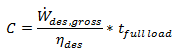
Storage volume |
|
|
TES thermal capacity |
|
|
Tank diameter |
|
|
Min fluid volume |
|
|
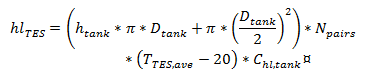
Estimated tank heat loss |
|
Equivalent to the product of the total interacting tank area, number of tank pairs, temperature difference with ambient, and heat loss coefficient |
TES fluid density |
|
Lookup function for density, evaluated at Fluid temperature |
TES specific heat |
|
Lookup function for specific heat, evaluated at Fluid temperature |