A thermal energy storage system (TES) stores heat from the solar field in a storage medium. Heat from the storage system can drive the power cycle or heat sink during periods of low or no sunlight. A thermal storage system is beneficial in many locations where the peak demand for power or heat occurs after the sun has set. Adding thermal storage to a parabolic trough system allows the collection of solar energy to be separated from the operation of the power cycle or heat sink. For example, a system might be able to collect energy in the morning and use it to deliver electricity or heat late into the evening.
In direct storage systems, the solar field's heat transfer fluid itself serves as the storage medium. In indirect systems, the solar field and storage fluids are separate, and heat is transferred from the solar field heat transfer fluid to the storage fluid through heat exchangers. The default thermal storage is a two-tank system that consists of one or more tank pairs, pumps to circulate the liquids, and depending on the design, heat exchangers. Each tank pair consists of a hot tank to store heat from the solar field, and a cold tank to store the cooled storage medium after the power block has extracted its energy.
The storage system variables describe the thermal energy storage system. The inputs on the System Control page determine when the system dispatches energy from the storage system.
Notes. For a detailed explanation of the physical trough model, see Wagner, M. J.; Gilman, P. (2011). Technical Manual for the SAM Physical Trough Model. 124 pp.; NREL Report No. TP-5500-51825. http://www.nrel.gov/docs/fy11osti/51825.pdf (3.7 MB) In versions of SAM released after February 2020, fossil backup is not available for the Physical Trough model because it was not incorporated into the new dispatch controller logic at the time of the software release. If you want to use fossil backup, use version SAM 2018.11.11, available on the SAM website Download page.
System Design Parameters
The system design parameters are from the System Design page where you can set their values, and are shown for reference on the Thermal Storage page.
Cycle thermal power, MWt
The power cycle thermal power input at design.
Hours of storage at design point, hours
The thermal storage capacity expressed in number of hours of thermal energy delivered at the design power cycle thermal power. The physical capacity is the number of hours of storage multiplied by the power cycle design thermal input. Used to calculate the thermal energy system's maximum storage capacity.
Loop outlet HTF temperature, ºC
The temperature of the HTF at the outlet of the loop under design conditions. During operation, the actual value may differ from this set point. This value represents the target temperature for control of the HTF flow through the solar field and will be maintained when possible.
Loop inlet HTF temperature, ºC
The temperature of HTF at the loop inlet under design conditions. The actual temperature during operation may differ from this value. SAM sets the power cycle's design outlet temperature equal to this value.
General Storage System Parameters
Fix diameter
Choose this option to define the tank dimensions based on the tank inner diameter.
Fix height
Choose this option to define the tank dimensions based on the tank height.
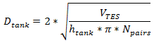
Tank inner diameter, m
The inner diameter of a storage tank, assuming that all tanks have the same dimensions.
If you choose Fix height, SAM calculates this value based on the tank height that you specify and the storage volume, where is the tank height, is the number of tank pairs, is the Storage Volume:
Tank height, m
The height of the cylindrical volume of heat transfer fluid in each tank.
If you choose Fix diameter, SAM calculates this value based on the tank diameter that you specify and the storage volume.
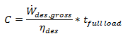
TES Thermal capacity, MWt-hr
The equivalent thermal capacity of the storage tanks, assuming the thermal storage system is fully charged. This value does not account for losses incurred through the heat exchanger for indirect storage systems.
SAM calculates the total heat transfer fluid volume in storage based on the storage hours at full load and the power block design turbine thermal input capacity. The total heat transfer fluid volume is divided among the total number of tanks so that all hot tanks contain the same volume of fluid, and all cold tanks contain the same volume of fluid.
Available HTF volume, m³
The total volume of storage fluid in both storage tanks.
SAM calculates the total heat transfer fluid volume in storage based on the storage hours at full load and the power block design turbine thermal input capacity. The total heat transfer fluid volume is divided among the total number of tanks so that all hot tanks contain the same volume of fluid, and all cold tanks contain the same volume of fluid.
Tank fluid minimum height, m
The minimum allowable height of fluid in the storage tank(s). The mechanical limits of the tank determine this value.
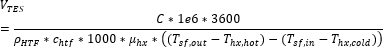
Storage tank volume, m³
The volume of the storage tank, calculated as follows were C is the TES thermal capacity
Parallel tank pairs
The number of parallel hot-cold storage tank pairs. Increasing the number of tank-pairs also increases the volume of the heat transfer fluid exposed to the tank surface, which increases the total tank thermal losses. SAM divides the total heat transfer fluid volume among all of the tanks, and assumes that each hot tank contains an equal volume of fluid, and each cold tank contains and equal volume.
Number of subtimesteps
Number of steps the simulation time step is subdivided into for the TES equations. The default value is 100.
Wetted loss coefficient, W/m2-K
The thermal loss coefficient for the storage tanks. This value specifies the number of thermal watts lost from the tanks per square meter of tank surface area and temperature difference between the storage fluid bulk temperature and the ambient dry bulb temperature.
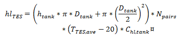
Estimated heat loss, MWt
The estimated value of heat loss from all storage tanks. The estimate assumes that the tanks are 50% charged, so that the storage fluid is evenly distributed among the cold and hot tanks, and that the hot tank temperature is equal to the solar field hot (outlet) temperature, and the cold tank temperature is equal to the solar field cold (inlet) temperature. Calculated as follows:
Pumping power for HTF through storage, kJ/kg
A coefficient used to calculate the electric power consumed by pumps to move heat transfer fluid through the storage heat exchanger on both the solar field side and the storage tank side (for cases where a heat exchanger exists, specified on the Thermal Storage page). This coefficient is applied separately to the solar field flow and the tank flow.
Initial hot HTF percent, %
The fraction of the storage heat transfer fluid in the hot storage tank at the beginning of the simulation.
Cold and hot tank heater set point, ºC
The minimum allowable storage fluid temperature in the storage tanks. If the fluid temperature falls below the set point, the electric tank heaters deliver energy to the tanks, attempting to increase the temperature to the set point. SAM reports this energy in the performance model results as "Tank freeze protection energy."
Cold and hot tank tank heater capacity, MWe
The maximum rate at which heat can be added by the electric tank heaters to the storage fluid in the tanks.
The two tank storage technology consists of pairs of tanks. Each pair has a hot and cold tank that stores HTF. In direct storage systems, hot HTF from the field directly fills the hot tank while cold HTF leaves the cold tank and returns to the field. When discharging, hot HTF leaves the hot tank to the power cycle, and the power cycle cold outlet fills the cold tank. In indirect systems, a heat exchanger transfers heat between the field HTF and storage HTF. Storage HTF transfers from the cold tank to the hot tank when charging, and vice versa when discharging.
Storage HTF fluid
The storage fluid used in the thermal energy storage system.
When the storage fluid and solar field heat transfer fluid (HTF) are different, the system is an indirect system with a heat exchanger (heat exchanger derate is less than one).
When the storage fluid and solar field HTF are the same, the system is a direct system that uses the solar field HTF as the storage medium. For a direct system, SAM disables the Hot side HX approach temp and Cold side HX approach temp variables, and sets the Heat exchanger derate value to one. See the Solar Field page for table of fluid properties.
User-defined HTF fluid
When you choose user-defined from the Storage HTF fluid list, you can specify a table of material properties of a storage fluid. You must provide values for two temperatures (two rows of data) of specific heat, density, viscosity, and conductivity values. See Custom HTF for details.
HTF density, kg/m3
The density of the storage fluid at the fluid temperature, used to calculate the total mass of thermal fluid required in the storage system.
Storage HTF min operating temp, ºC
The minimum HTF operating temperature recommended by the HTF manufacturer.
In some cases the minimum operating temperature may be the same as the fluid's freeze point. However, at the freeze point the fluid is typically significantly more viscous than at design operation temperatures, so it is likely that the "optimal" minimum operating temperature is higher than the freeze point.
Storage HTF max operating temp, ºC
The minimum HTF operating temperature recommended by the HTF manufacturer.
Operation at temperatures above this value may result in degradation of the HTF and be unsafe. To avoid this, you may want to include a safety margin and use a maximum operating temperature value slightly lower than the recommended value.
Notes. SAM displays the operating temperature limits for your reference so you can compare them to the storage temperatures reported in the results to ensure that they do not exceed the limits. SAM does not adjust the system's performance to avoid exceeding these operating limits. SAM only displays these limits for fluids that are in SAM's library. If you use a custom HTF instead of one from the SAM library, SAM disables the HTF operating temperature limits. In this case, you should use data from the fluid manufacturer specifications.
Hot side HX approach temp, ºC
Applies to systems with a heat exchanger only (indicated by a heat exchanger derate value of less than one). The temperature difference on the hot side of the solar-field-to-thermal-storage heat exchanger. During charge cycles, the temperature is the solar field hot outlet temperature minus the storage hot tank inlet temperature. During discharge cycles, it is defined as the storage hot tank temperature minus the power cycle hot inlet temperature.
Cold side HX approach temp, ºC
Applies to systems with a heat exchanger only (indicated by a heat exchanger derate value less than one). The temperature difference on the cold side of the solar field-to-thermal-storage heat exchanger. During charge cycles, the temperature is the storage cold temperature (storage outlet) minus the heat exchanger cold temperature. During discharge cycles, it is the heat exchanger cold temperature minus the storage cold temperature (storage inlet).
Note. SAM sets the cold side approach temperature equal to the hot side temperature because SAM assumes a counter-flow heat exchanger, and this simplification reduces the number of design inputs.
The packed bed storage technology consists of a tank filled with a packed bed of solid media (e.g. rocks, spheres, etc.) that stores thermal energy passed via an HTF. When charging, hot HTF enters the tank and heats the solids closest to the inlet. As the solids heat, the thermal gradient travels down the tank. The HTF exits the tank on the other end at a low temperature. During discharge, cold HTF enters the opposite side of the tank and exits at a high temperature. This process moves the thermal gradient up the tank.
The tank model is subdivided spatially along the thermal gradient. The solid media and HTF are assumed to have equal temperatures in each subsection. The SAM timestep is divided into subtimesteps. This one-temperature model is based on the work of Vortmeyer and Schaefer.
•Vortmeyer, D., and R. J. Schaefer. “Equivalence of One- and Two-Phase Models for Heat Transfer Processes in Packed Beds: One Dimensional Theory.” Chemical Engineering Science 29, no. 2 (February 1, 1974): 485–91. https://doi.org/10.1016/0009-2509(74)80059-X.
Packed Bed TES Parameters
Number of spatial sections
Number of subsections the model divides the thermal gradient into.
Max decrease in hot discharge temp, ºC
The maximum allowable decrease in temperature on the hot side of the packed bed tank when discharging. Determines how much energy in the TES can be discharged while maintaining the shape of the thermocline.
Max increase in cold charge temp, ºC
The maximum allowable increase in temperature on the cold side of the packed bed tank when charging. Determines how much energy the TES can charge while maintaining the shape of the thermocline.
Min charge temp, ºC
The minimum allowable HTF inlet temperature when charging the tank. Helps maintain the thermocline shape and prevents the controller from charging the TES with low temperature heat.
Void fraction
The fraction of space in the tank that is not solid media.
Volume oversize factor
Factor to increase the size of tank volume to account for thermocline shape. The volume is calculated based on design power and storage duration but does not account for shape of the thermocline.
Solid media density, kg/m3
The density of the packed bed solid media.
Solid media specific heat, kJ/kg K
The specific heat of the packed bed solid media.
Effective conductivity, W/m K
The effective conductivity of the packed bed, which considers conductivity of the solid media and HTF.
The pressurized water cylinder with piston separator storage technology consists of one tank with a piston separating the hot and cold sections of the tank. When the storage is fully discharged, the tank is filled with cold HTF. As the storage charges, the hot side of the tank fills with hot HTF and the piston moves along the tank, reducing the size of the cold section. When the tank is fully charged, it is filled with hot HTF. The tank is filled with HTF at all times to maintain pressure.
Piston Cylinder TES Parameters
Tank wall thickness, m
The thickness of the tank wall, used to calculate the tank wall mass.
Tank wall specific heat, kJ/kg K
The specific heat of the tank wall, used to account for the thermal mass of the tank wall.
Tank wall density, kg/m3
The density of the tank wall, used to calculate the tank wall mass.
Additional wall mass due to insulation, %
Tank insulation can be modeled by adding additional mass to the wall.
Piston loss (%) as a function of mass flow rate x (kg/s)
As the tank charges and discharges, fluid leaks through the piston from the expanding side of the tank to the contracting side. The amount of leakage is a function of the charge/discharge mass flow rate.
 is the tank height,
  is the number of tank pairs,
  is the Storage Volume: